Question 3: Explain the experimental arrangements for the production of interference fringes by Young’s double slit experiment and get an expression for the fringes space.
ANSWER
In 1801, Thomas Young performed his double slit experiment to verify the wave theory of light. Young split the wave front from the monochromatic light in two parts and allowed them to interfere. As the wave fronts were from the same source, they were phase coherent.
Experimental Arrangements
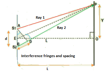
The experimental arrangement consists of a source of monochromatic light ‘S’. Light from source ‘S’ falls on slit ‘S0‘. There he provided two other slits S1 and S2 as shown in the diagram. Both slits S1 and S2 are very close to one another and are parallel to slit S0. A screen is placed at a distance D beyond the slits S1and S2.

Theory
Now under this experimental arrangement, a beam of monochromatic light is passed through the slit S0. The slit S0 sends out circular wave fronts in accordance with Huygens’s Principle. The same wave front reaches at slits S1 and S2. The wavelets from S1 and S2 are now in phase because they belong to the same wave front. In this way two waves in phase with one another are obtained. This method is called division of wave front. As the two slits S1 and S2 are very small, and are comparable to the wave length of light in fact, diffraction of light from both slits occurs and the light is spread into the region beyond slits S1and S2. This causes superposition of waves from the two slits and we observe the interference pattern on the screen.
Interference Fringes and Fringe Spacing
In order to get expressions for bright and dark fringes (called maxima and minima, respectively) and spacing between them, we consider the figure.
For constructive interference or bright fringe, the equation is,
Path difference = d = 0, λ, 2λ, 3λ, ——
For the central point ‘O’, the path difference of the waves from the slits S1 and S2 is zero; hence there would be constructive interference or a bright fringe.
For other points on the screen, say p, however, the wave from slit S2 covers a distance s = BD more than the wave from slit S1. From the right-angle-triangle ABD,
Path difference = BD = s = dsinθ
∴ the condition for constructive interference becomes,
dsinθ = mλ
Where m = 0, ±1, ±2, ±3,……..
For m = 0 represents the central point and for m = ±1 the first order maxima above and below the central point and m = ±2, the second order maxima above and below the central point and so on.
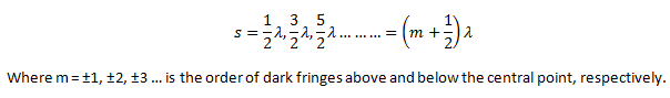
Similarly, for destructive interference at any point p on the screen, the condition for path difference is,
Location of fringes or fringe spacing
Consider triangle EOP in the above diagram. We know that;
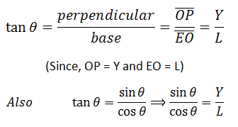
In actual experiments, however, point P is very close to point O. Which means that theta is almost equal to zero degrees.
Now, cos0° = 1, the above equation becomes, Y/L = sinθ
Comparing this equation with the equation for the path difference, i-e, s =d sinθ and rearranging, we have,

Where Y gives the position of the point of interference.
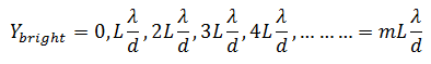
So, for constructive interference, the condition is
s = 0, λ, 2λ, 3λ, …
Put these values of path difference in the above equation, the bright fringes are,
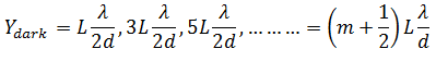
For dark bands, the condition of path difference is
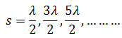
Put these values of path difference in the above equation,the dark fringes are,
Fringe Spacing
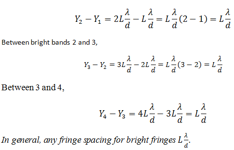
Fringe spacing is the distance between two consecutive maxima or two consecutive minima. Therefore,
Fringe spacing for bright bands 1 and 2,
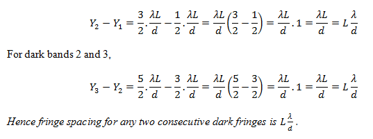
Similarly, fringe spacing for the dark bands 1 and 2,
Pingback:huygens-principle – msa
Pingback:diffraction-of-x-rays – msa
Pingback:Comprehensive Questions, Physical Optics … msa – msa
Pingback:Physical Optics, Comprehensive Questions … msa – msa
Pingback:index-cq-ch9-p11 – msa