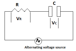
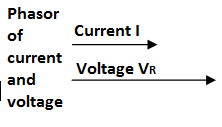
1. The potential drop VR across the resistance R is in phase with the current I. So

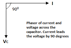
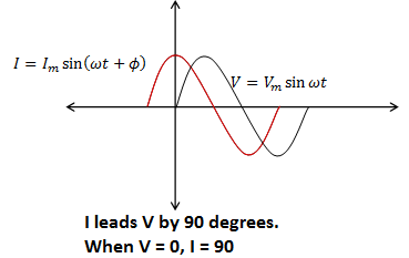
2. Potential drop VC across the capacitance C lags behind the current I by π/2 rad. So if,

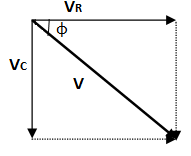
The phasor diagram is shown below.
1. The potential drop VR across the resistance R is in phase with the current I. So
2. Potential drop VC across the capacitance C lags behind the current I by π/2 rad. So if,
The phasor diagram is shown below.
Pingback:lq-ch-15-p12 – msa