Menu Close

Question 7: What is galvanometer? How it is converted into an ammeter and a voltmeter?

Answer

Definition of Galvanometer

“A moving coil galvanometer is an instrument used for the detection and measurement of small electric currents”.

Principle of working

Whenever current is passed through a coil suspended in a magnetic field, a torque is exerted on the coil. The torque produced in the coil is used as the basic principle of the galvanometer.

Construction and theory

Consider the figure below. The coil C with a large number of turns (usually of thin copper) is suspended between the poles of permanent U-shaped magnet by a fine metallic ribbon (In the fig below the two poles of the U-shaped magnet are shown). The poles are made concave and a soft iron cylinder placed between them. This arrangement makes the field radial and stronger on the plane of the coil. T1 and T2 are connections to the coil. Some pointer or mirror M is used to measure the angular deflection of the coil.

Diagram of a moving coil galvanometer

Suppose a current I is passed through the coil, having area A. Let the number of turns in the coil are N and the value of the magnetic field is B. Then we know the torque produced in the coil is, Ʈ =N IAB cosα
Here α is the angle between the direction of the plane of the coil and the direction of B. The field is radial and α = 00. Therefore, τ = NIAB

Under the action of this torque the coil rotates and the suspension ribbon twisted. The twist in the ribbon produces a restoring torque. The coil will rotate until it is in equilibrium under the action of both torques. The restoring torque of the ribbon is proportional to the angle 𝛉 through which the ribbon is twisted.

Ʈres ∝ ⇒ Ʈres = C 𝛉

Here C is a constant measuring the torque for unit twist of the coil.

When the coil is in equilibrium, the deflecting and restoring torques are equal.

Now C, N (no of turns of the coil), A (area of the coil) and magnetic field B are constants therefore, the whole term (C/NAB) is constant. Therefore,

Hence, equation (1) can be used to detect and measure the current for a known value of θ.

Calibration

Deflection of the coil (or angle θ) can be measured by two methods;

(a) Lamp-mirror scale method

It is used for high sensitivity requirements and non-portable situations (means it may not need to be moved from one place to another; like fixed in labs). The deflection θ is observed with a small mirror M attached to the coil. A beam of light from the lamp falls upon the mirror and the reflected beam (from the mirror) is incident on a translucent (half transparent) scale at a distance 1 m from the galvanometer. When the mirror rotates with torque due to the current in the coil the spot light moves along the scale. This displacement of the spot on the scale is proportional to the angle of deflection θ. Hence, the deflection is calculated from the calibrated scale.

(b) Index needle method

This method is used in less sensitive and portable galvanometers. One type of this is d’ Arson Val galvanometer. The coil is pivoted between two jeweled bearings and the restoring torque is provided by hair springs also serve as current leads. A light pointer attached to the coil moves over a calibrated scale, measuring the deflection and hence the current.

Conversion of Galvanometer to Ammeter

Ammeter

Ammeter is a device used for the measurement of large currents in electric circuits.

A galvanometer is very sensitive instrument and a small amount of current can take the pointer out of the scale. Therefore, for large currents we need an instrument that can measure large currents. An ammeter can successfully serve this purpose.

A galvanometer can be modified to obtain a large current measuring ammeter. Let we want to construct an ammeter which can measure current I Ampere.

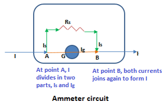
Suppose the galvanometer has a coil resistance of Rg and gives full deflection when current Ig is passed through it. Now for conversion purpose, we connect a low resistance Rs, called shunt, in parallel with the terminals of the galvanometer coil. When large current I flows in the circuit, it divides at point A with Ig goes into the galvanometer and the remaining portion (I – Ig) passes through the shunt. Suppose this current is denoted by Is. Since both galvanometer and the shunt are in parallel, the potential difference across both is same, or, Vg = Vs = V. Therefore, applying Ohm’s law, Vg = Ig Rg and Vs = Is Rs

Or Ig Rg = Is Rs ⇒ Ig Rg = (I-Ig) Rs ⇒ Ig Rg/ (I-Ig) = Rs

The shunt resistance thus determined when connected will convert the given galvanometer into an ammeter and will give full scale deflection when current I is passing through the main circuit.

In order to have more than one range in the ammeter, more than one shunt are connected and the desired range of the current is selected for the current in the main circuit.

Conversion of Galvanometer to voltmeter

Voltmeter

It is an electric device used to measure the potential difference between two points.

A galvanometer is a very sensitive instrument and can’t be used for large potential differences. Therefore, a galvanometer is properly modified to convert it to a voltmeter suitable for measuring high voltages.

Here we go to convert a galvanometer into a voltmeter to measure a maximum voltage of V volts. Let Rg be the resistance of the galvanometer and it gives full scale deflection when a current Ig is passed through it. For conversion, we connect a high resistance Rh in series with the galvanometer. In this way the current reaches the galvanometer in a controlled manner. The value of Rh should be such that the voltage V produces current Ig in the series combination of Rg and Rh. Now,

V = Ig Rg+ Ig Rh or V = Ig (Rg + Rh)

V/Ig = Rg + Rh or Rh = V/Ig – Rg

Hence by connecting Rh in series, the galvanometer is converted into a voltmeter of range 0 to V volts.

2 Comments

  1. Pingback:amperes-law-expression-for-a-solenoid – msa

  2. Pingback:Electromagnetism, Physics 12 … msa – msa

Leave a Reply

Your email address will not be published. Required fields are marked *